**Custom AXI-Streaming Module**
**Home Page**
This lab assumes you've already gone through the whole development cycle of building a DMA-interfaced piece of programmable Logic that can be accessed through Python. If you haven't done that, please watch /this video here since we basically build right off of it. In fact, it might be a good idea to simply **Save As** a working version of the system demonstrated in that project page/video and then replace the FIR filter
A Simple Non-Delayed Pass-Through
=======================
The first Custom AXI-streaming module we'll write will delay the input data $x$ handed to it by one clock cycle and pass out $3x +10000$. In order to get started go to **`Tools>Create and Package New IP`** and after clicking **`Next`**, specify that you'd like to **`AXI4 Peripheral`** (just like we've done before).
In the next window that comes up, name it whatever you want. I called my function `joe7` since I don't make good choices in naming things and will inevitably forget what that IP does, but it doesn't matter. We probably won't be using this IP long term. Call it something and move on.
Keep clicking, and then choose to **`Edit the IP`** now (rather than later, though you can always do that). Once everythign loads up your AXI-Streaming module will be comprised of three Verilog files. A high level one, and then two other modules (one running the Slave and one running the Master side of your module.). They're supposed to provide some sort of FIFO functionality when used together, but I wasn't able to make 100% sense of what they're doing (and it is overkill for what we need to do), so I erased all reference to them in the high level module, and instead added some basic "pass-through" code that basically passes forward (with a one-clock cycle latency because of the registers I added) signals from one side to the other as needed.
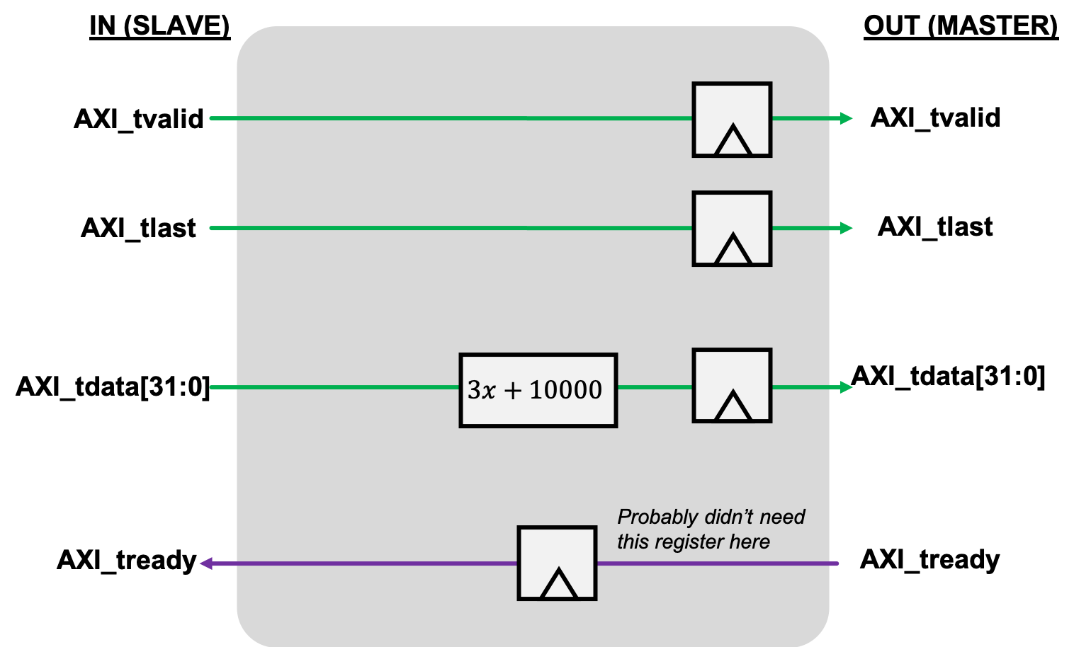
I added this logic directly into the Verilog module below since it was pretty simple. I also added some reset stuff just to be thorough, but you can probably skip that. Update the code in your module to reflect the logic here. If you let Vivado auto-name the ports, you should be able to copy-paste this stuff right in (module name differences aside).
~~~~~~~~~~~~~~~~~~~~~~~~~~~~~~~~~~~ c linenumbers
module joe7_v1_0 #
(
// Users to add parameters here
// User parameters ends
// Do not modify the parameters beyond this line
// Parameters of Axi Slave Bus Interface S00_AXIS
parameter integer C_S00_AXIS_TDATA_WIDTH = 32,
// Parameters of Axi Master Bus Interface M00_AXIS
parameter integer C_M00_AXIS_TDATA_WIDTH = 32,
parameter integer C_M00_AXIS_START_COUNT = 32
)
(
// Users to add ports here
// User ports ends
// Do not modify the ports beyond this line
// Ports of Axi Slave Bus Interface S00_AXIS
input wire s00_axis_aclk,
input wire s00_axis_aresetn,
output wire s00_axis_tready,
input wire [C_S00_AXIS_TDATA_WIDTH-1 : 0] s00_axis_tdata,
input wire s00_axis_tlast,
input wire s00_axis_tvalid,
// Ports of Axi Master Bus Interface M00_AXIS
input wire m00_axis_aclk,
input wire m00_axis_aresetn,
output wire m00_axis_tvalid,
output wire [C_M00_AXIS_TDATA_WIDTH-1 : 0] m00_axis_tdata,
output wire m00_axis_tlast,
input wire m00_axis_tready
);
reg m00_axis_tvalid_reg;
reg m00_axis_tlast_reg;
reg [C_M00_AXIS_TDATA_WIDTH-1 : 0] m00_axis_tdata_reg;
reg s00_axis_tready_reg;
assign m00_axis_tvalid = m00_axis_tvalid_reg;
assign m00_axis_tlast = m00_axis_tlast_reg;
assign m00_axis_tdata = m00_axis_tdata_reg;
assign s00_axis_tready = s00_axis_tready_reg;
always @(posedge s00_axis_aclk)begin
if (s00_axis_aresetn==0)begin
s00_axis_tready_reg <= 0;
end else begin
s00_axis_tready_reg <= m00_axis_tready;
end
end
always @(posedge m00_axis_aclk)begin
if (m00_axis_aresetn==0)begin
m00_axis_tvalid_reg <= 0;
m00_axis_tlast_reg <= 0;
m00_axis_tdata_reg <= 0;
end else begin
m00_axis_tvalid_reg <= s00_axis_tvalid;
m00_axis_tlast_reg <= s00_axis_tlast;
m00_axis_tdata_reg <=3*s00_axis_tdata+10000;
end
end
endmodule
~~~~~~~~~~~~~~~~~~~~~~~~~~~~~~~~~~~
After it is built, package this IP up, and add an instance of the IP to your system, connect it up just like you did with the FIR filter, and then run the auto-connection subroutine a few times when it prompts you. Afterwards you should have something that looks like this:
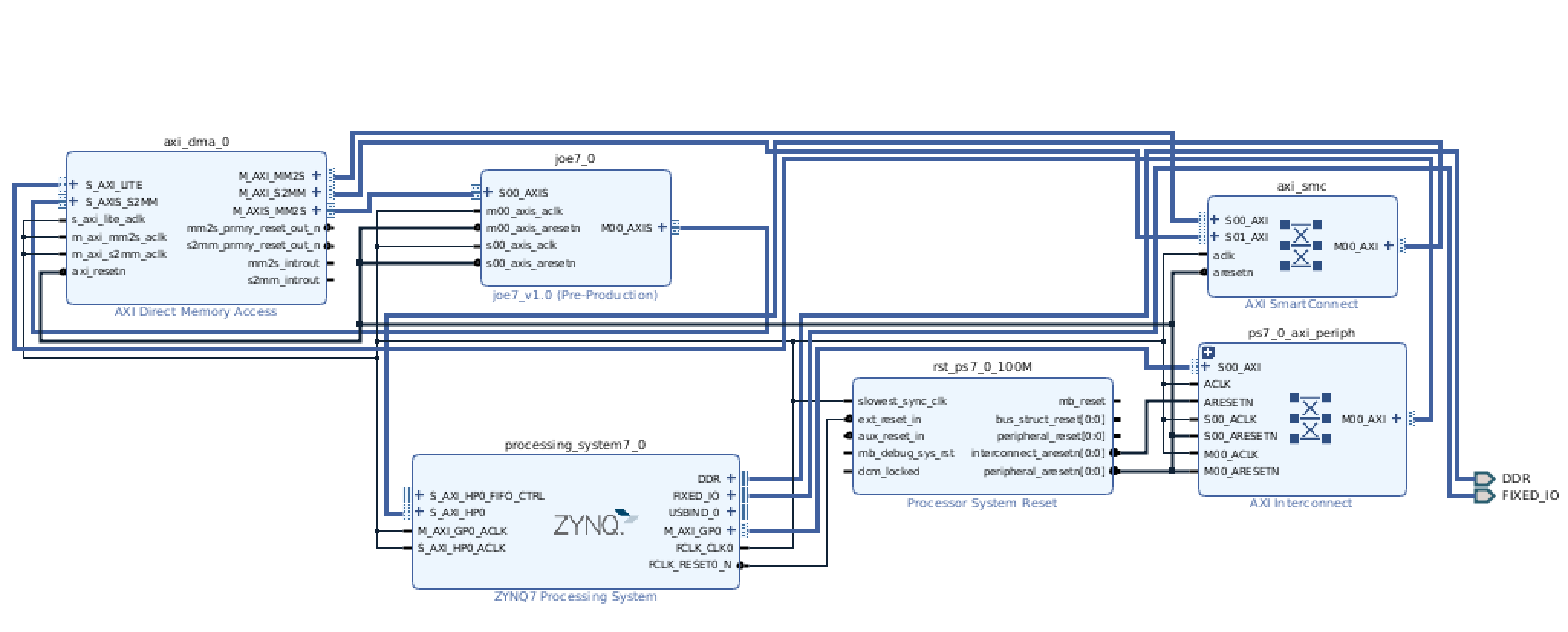
Do the regular build stuff, and then let's get ready to interact with it in Python!
Test with Python
===================
Assuming you built everything properly and move the bit and tcl files up to the web, the following two scripts, when run in sequence, should generate some data using numpy, and then perform our mathematical operation $3x+10000$ on the data in both software and hardware and compare (very similar to the excellent hardare accelerator video referenced earlier where they used a FIR filter).
The first one loads everything up:
~~~~~~~~~~~~~~~~~~~~~~~~~~~~~~~~~~~ python linenumbers
from pynq import Overlay
import pynq.lib.dma
%matplotlib notebook
import matplotlib.pyplot as plt
def plot_to_notebook(time_sec,in_signal,n_samples,out_signal=None):
plt.figure()
plt.subplot(1, 1, 1)
plt.xlabel('Time (usec)')
plt.grid()
plt.plot(time_sec[:n_samples]*1e6,in_signal[:n_samples],'y-',label='Input signal')
if out_signal is not None:
plt.plot(time_sec[:n_samples]*1e6,out_signal[:n_samples],'g-',linewidth=2,label='Module output')
plt.legend()
overlay = Overlay('./st.bit') #./dmatest2.bit
print(overlay.ip_dict)
dma = overlay.axi_dma_0
import numpy as np
# Total time
T = 0.02
# Sampling frequency
fs = 100e6
# Number of samples
n = int(T * fs)
# Time vector in seconds
t = np.linspace(0, T, n, endpoint=False)
# Samples of the signal
samples = 10000*np.sin(0.2e6*2*np.pi*t) + 1500*np.cos(46e6*2*np.pi*t) + 2000*np.sin(12e6*2*np.pi*t)
# Convert samples to 32-bit integers
samples = samples.astype(np.int32)
print('Number of samples: ',len(samples))
# Plot signal to the notebook
plot_to_notebook(t,samples,1000)
~~~~~~~~~~~~~~~~~~~~~~~~~~~~~~~~~~~
and then this one which runs the actual software/hardware comparison test:
~~~~~~~~~~~~~~~~~~~~~~~~~~~~~~~~~~~ python linenumbers
from scipy.signal import lfilter
import time
start_time = time.time()
sw_fir_output = 3*samples+10000
stop_time = time.time()
sw_exec_time = stop_time - start_time
print('Software execution time: ',sw_exec_time)
# Plot the result to notebook
plot_to_notebook(t,samples,1000,out_signal=sw_fir_output)
from pynq import Xlnk
import numpy as np
# Allocate buffers for the input and output signals
xlnk = Xlnk()
in_buffer = xlnk.cma_array(shape=(n,), dtype=np.int32)
out_buffer = xlnk.cma_array(shape=(n,), dtype=np.int32)
# Copy the samples to the in_buffer
np.copyto(in_buffer,samples)
# Trigger the DMA transfer and wait for the result
import time
start_time = time.time()
dma.sendchannel.transfer(in_buffer)
dma.recvchannel.transfer(out_buffer)
dma.sendchannel.wait()
dma.recvchannel.wait()
stop_time = time.time()
hw_exec_time = stop_time-start_time
print('Hardware execution time: ',hw_exec_time)
print('Hardware acceleration factor: ',sw_exec_time / hw_exec_time)
# Plot to the notebook
plot_to_notebook(t,samples,1000,out_signal=out_buffer)
# Free the buffers
in_buffer.close()
out_buffer.close()
~~~~~~~~~~~~~~~~~~~~~~~~~~~~~~~~~~~
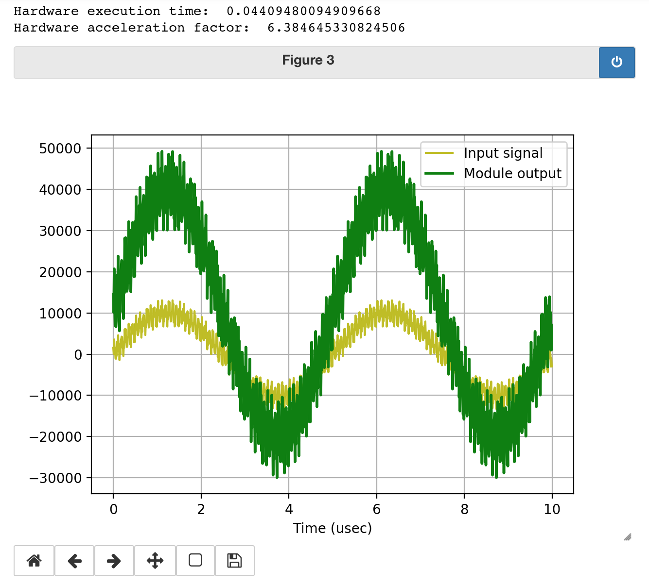
When you run the code, you should get something similar to the following for an output. The $3x+10000$ operation is carried out on 2 million values and it looks like it worked!
Awesome! We've just written an AXI-Streaming module that performs some relatively simple operation from scratch! Behold our power.
!!! note
Maybe "Save As" your whole project at this point if you're not using Version control, since we're going to change our IP in the next section.
A Slightly More Complicated Pass-Through
============================
Let's delete the instance of our custom AXI-streaming module from the previous section and instead now create another module that basically does the same thing, however it will have a data throughput of half that of our previous module. Specifically one even clock cycles, it will act like the module up above, but on odd clock cycles, it will freeze the entire pipeline. This is a very basic state machine, of course. In order to do this, I create a state variable below `waiting_state`, and basically when this module is not in the waiting state, it acts exactly like module we previously created, but when it is in the waiting state (`waiting_state ==1`), the module "freezes" everything, which means it pulls its Master `TVALID` line low (to tell the downstream slave device that the data flow has stopped), and also pulls its Slave `TREADY` low (to tell the upstream master device that flow needs to stop). Try to read through the Verilog (at the bottom)
~~~~~~~~~~~~~~~~~~~~~~~~~~~~~~~~~~~ c linenumbers
module joe8_v1_0 #
(
// Users to add parameters here
// User parameters ends
// Do not modify the parameters beyond this line
// Parameters of Axi Slave Bus Interface S00_AXIS
parameter integer C_S00_AXIS_TDATA_WIDTH = 32,
// Parameters of Axi Master Bus Interface M00_AXIS
parameter integer C_M00_AXIS_TDATA_WIDTH = 32,
parameter integer C_M00_AXIS_START_COUNT = 32
)
(
// Users to add ports here
// User ports ends
// Do not modify the ports beyond this line
// Ports of Axi Slave Bus Interface S00_AXIS
input wire s00_axis_aclk,
input wire s00_axis_aresetn,
output wire s00_axis_tready,
input wire [C_S00_AXIS_TDATA_WIDTH-1 : 0] s00_axis_tdata,
input wire [(C_S00_AXIS_TDATA_WIDTH/8)-1 : 0] s00_axis_tstrb,
input wire s00_axis_tlast,
input wire s00_axis_tvalid,
// Ports of Axi Master Bus Interface M00_AXIS
input wire m00_axis_aclk,
input wire m00_axis_aresetn,
output wire m00_axis_tvalid,
output wire [C_M00_AXIS_TDATA_WIDTH-1 : 0] m00_axis_tdata,
output wire [(C_M00_AXIS_TDATA_WIDTH/8)-1 : 0] m00_axis_tstrb,
output wire m00_axis_tlast,
input wire m00_axis_tready
);
reg m00_axis_tvalid_reg;
reg m00_axis_tlast_reg;
reg [C_M00_AXIS_TDATA_WIDTH-1 : 0] m00_axis_tdata_reg;
reg s00_axis_tready_reg;
reg waiting_state; //register to contain our toggle state
assign m00_axis_tvalid = m00_axis_tvalid_reg;
assign m00_axis_tlast = m00_axis_tlast_reg;
assign m00_axis_tdata = m00_axis_tdata_reg;
assign s00_axis_tready = s00_axis_tready_reg;
always @(posedge s00_axis_aclk)begin
if (s00_axis_aresetn==0)begin
s00_axis_tready_reg <= 0;
end else begin
if (waiting_state)begin //if waiting...
s00_axis_tready_reg <= 0; //tell the input master we're "paused"
end else begin //if we're not waiting:...
s00_axis_tready_reg <= m00_axis_tready;//back-propagate whatever the downstream modules want
end
end
end
always @(posedge m00_axis_aclk)begin
if (m00_axis_aresetn==0)begin
m00_axis_tvalid_reg <= 0;
m00_axis_tlast_reg <= 0;
m00_axis_tdata_reg <= 0;
end else begin
waiting_state = ~waiting_state; //toggle waiting state every time
if (waiting_state)begin
m00_axis_tvalid_reg <= 0; //pausing the release of information;
m00_axis_tlast_reg <= s00_axis_tlast;
m00_axis_tdata_reg <=0
end else begin
m00_axis_tvalid_reg <= s00_axis_tvalid;
m00_axis_tlast_reg <= s00_axis_tlast;
m00_axis_tdata_reg <=3*s00_axis_tdata+10000;
end
end
end
endmodule
~~~~~~~~~~~~~~~~~~~~~~~~~~~~~~~~~~~
Note that an important aspect of this design is that I set the correct signals for both upstream and downstream of our module so that the entire data pipeline doesn't get messed. We want to make sure that we tell the Master device (from the perspective of this module, it'll be the AXI-DMA out) that we're not sending data out so we shouldn't assume we're taking in data (since our module lacks a FIFO and therefore an ability to absorb this "buildup"). Similarly we need to tell the downstream Slave to not interpret what's our data line as data during the waiting_state.
Implement this new code, package the IP, and add it into your overall data pipeline like you did before. Run auto-connect if you need to, then rebuild your HDL wrapper, Regenerate the Bit File, and eventually move the appropriate files back up to the PS (name them something different so you can always do a comparison later on)
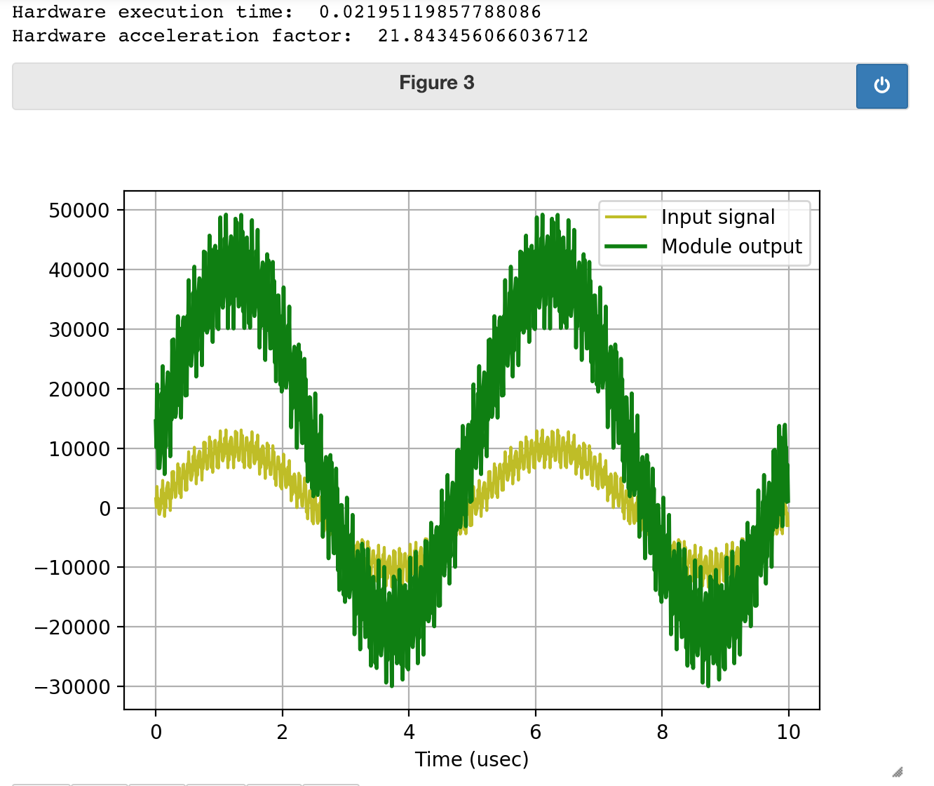
Test with Python
===================
Once the new files are back up, load the new bit file and run the code again just like before! What you should see as a result is the same exact output on the plot, but you'll notice that it took a lot longer for the data to make it through. That's because of our change! It now takes two clock cycles of the AXI clock to pass one "beat" of data whereas before it took only one. Since we're sending through 2 million bits of data (feel free to run `len(out_buffer)` to verify), and the AXI clock is 100 MHz, that means there should be an increase in time to process of $2\times 10^6 \cdot 10 \text{ ns} = 20 \text{ ms}$ and Holy Guacamole, that's just about what we see! We can make a difference as shown below when I run the Python on my slower module: