**SPI Control**
**Home Page**
In this blob we'll look at interfacing with a more complex memory-mapped device that allows us to communicate conveniently with other devices over SPI. We'll use an MPU9255 IMU for our specimen. Talk to Gim or Joe to get a IMU board with the appropriate pins.
Getting Started
=======================
Make a new project for the Pynq board. Make sure to target the board. Use your standard `xdc` file. Create a new block diagram, add in a Zynq Processing System, and run the default automation.
Under IP search for "AXI Quad SPI", and add one of those to your design. Configure it by double-clicking on it and set it up like shown (pretty close to the defaults)

After that is done, we need to interface to our SPI pins that we'll be using. There's a few ways to do it, but one easy way is to hop on over to the **`Board`** field which should be in the same mini-window as your **`Sources`** field. When in the **`Board`** field, it gives you a list of pre-configured/characterized inputs and outputs on the PYNQ Z2 board. Find the **`Arduino SPI CNN1`** Interface Port and drag it into your design. Wire it up to the **`SPI_0`** output of your AXI Quad SPI controller that you have.
After that, run automation. Your system should look like the following (approximately):
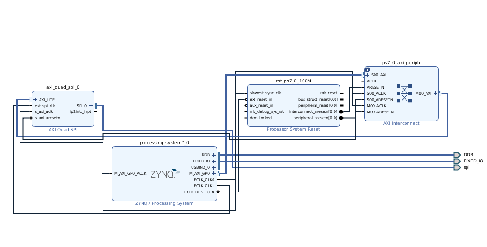
If it looks good, and is verified, add an HDL wrapper, and start the build process. While the system is running/building, feel free to move onto the wiring portion:
Wiring
===================
We need to connect six wires as shown in the figure below:
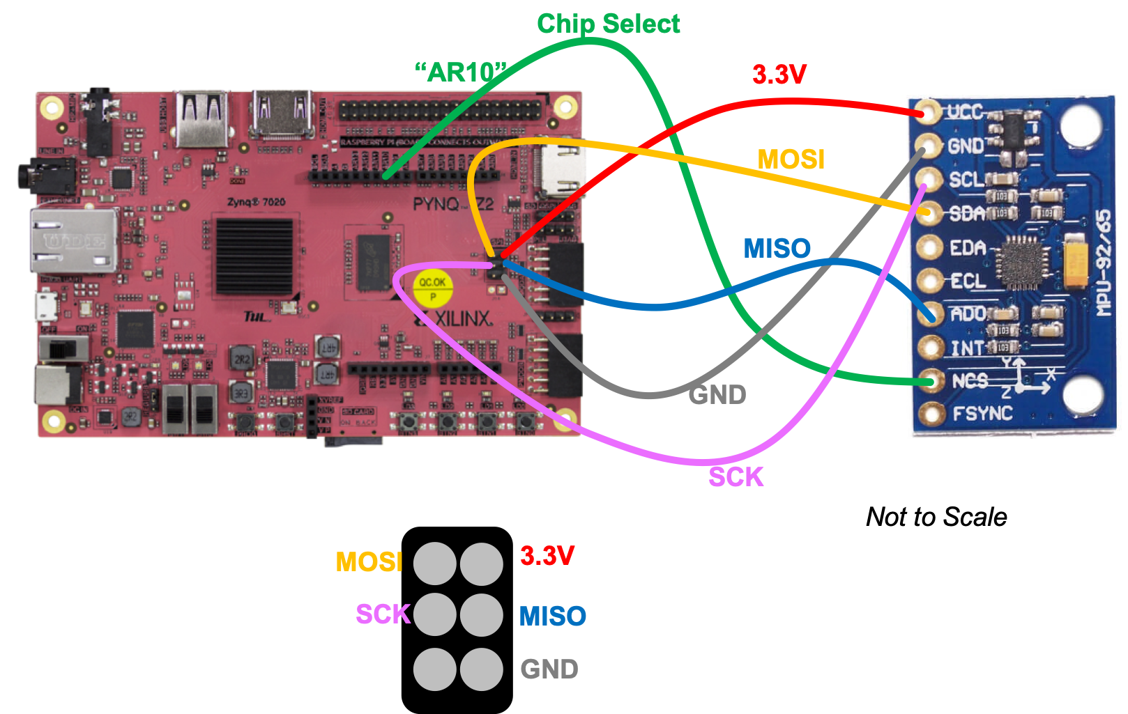
Once completed, move on with life.
Probably by the time your wiring is done, the project will be completed building. If all is good with no errors, export your block diagram to get your tcl file, and move it onto the PS for use with Python. You know the drill.
Interacting With It In Python
=========================
Once your bit file and tcl file are in place in the file structure of your system, go ahead and create either a new Python file or a Jupyter notebook. Make sure it is placed in the same relative file path as your bit file and tcl file from this lab. In my particular code I called them `spi3.bit` and `spi3.tcl` (since the first two failed) and you can see that in the code below.
First I basically import the bit file and then and then put the Memory-mapped IP into a convenient to use variable (variable `s` in this case).
~~~~~~~~~~~~~~~~~~~~~~~~~~~~~~~~~~~ python linenumbers
from pynq import Overlay #import the overlay module
import numpy as np
ol = Overlay('./spi3.bit') #locate/point to the bit file
print(ol.ip_dict)
s = ol.axi_quad_spi_0
print(s)
~~~~~~~~~~~~~~~~~~~~~~~~~~~~~~~~~~~
Then what I do is run the following blob. I went and opened up the data sheet for the SPI-AXI IP, studied it, and saw that in order to configure the device, I needed to set a few bits in the SPI Control Register which has the memory address `0x60` (page 25 of the datasheet). First I read the `0x60` AXI-SPI IP register which just tells me what the current mode is. Then I specified the ten bits in it in order to get it into the right mode. Feel free to check out what each bit does and compare to what we set.
After that we set the slave-select register `0x70`, which
~~~~~~~~~~~~~~~~~~~~~~~~~~~~~~~~~~~ python linenumbers
val = s.read(0x60)
print("Initial Register Setup: ")
print(np.binary_repr(val))
print(np.binary_repr(val))
s.write(0x60,0b00_00011110)
val = s.read(0x60)
print("Setup Now: ")
print(np.binary_repr(val))
#select device 0
s.write(0x70,0b1111_1110) #write teh lowest slave low (Active low so this one gets turned on.)
val = s.read(0x70)
print("SSelect: ")
~~~~~~~~~~~~~~~~~~~~~~~~~~~~~~~~~~~
To make a reading of the `0x75` register of the MPU9255, we need to:
* Write ten bits to reset the RX FIFO pointer (to the control register of the AXI-SPI controller)
* Write ten bits to un-reset (back to normal operation) the FIFO pointer (to the control register of the AXI-SPI controller)
* Write 8 bits (1 bit to read, followed by 7 bits of the MPU9255 address we care about (`0x75`)), and then 8 bits of 0 to pad and give the MPU9255 time to respond.
* We then read from the RX FIFO of the AXI-SPI controller and print out what we get, which should hopefully have `0x73` contained within!
~~~~~~~~~~~~~~~~~~~~~~~~~~~~~~~~~~~ python linenumbers
s.write(0x60,0b00_01011110) #reset RX FIFO
s.write(0x60,0b00_00011110) #run it again
s.write(0x68,0b11110101_00000000) #read WHO AM I register (should be 0x73)
val = s.read(0x6C)
print(np.binary_repr(val))
~~~~~~~~~~~~~~~~~~~~~~~~~~~~~~~~~~~
Once nicely wrapped into some other functions, this interface which we have here, while a bit cumbersome, allows us easy, access to chips that we may connect to our system, and what's great is that this is all in a relatively easy-to-develop language (Python) rather than something way low level which can make the inevitable process of debugging the registers of whatever device you're talking to a pain.