**Camera Board Info**
# Overview
The FPGA files are here:
* XDC file
* Top Level SV
* Camera Reading SV
The example code below will take the video from a camera (assuming it is set in QVGA mode which is 320 by 240 pixels which has been specified by the microcontroller), store it in a frame buffer, and then use that frame buffer to render the video at either 1X or 2X magnification on a display.
The camera board is a two-PMOD-port board comprised of an OV7670 camera, and a microcontroller used to initialize it. Using an external microctonroller greatly reduces the dev time and overhead on the FPGA. The FPGA drives the set-up camera by providing a clock signal directly to the camera and then the camera returns a clock signal back as well as data that can be interpretted to make an image. The camera can either be used with PMOD ports JA and JB or JC and JD.
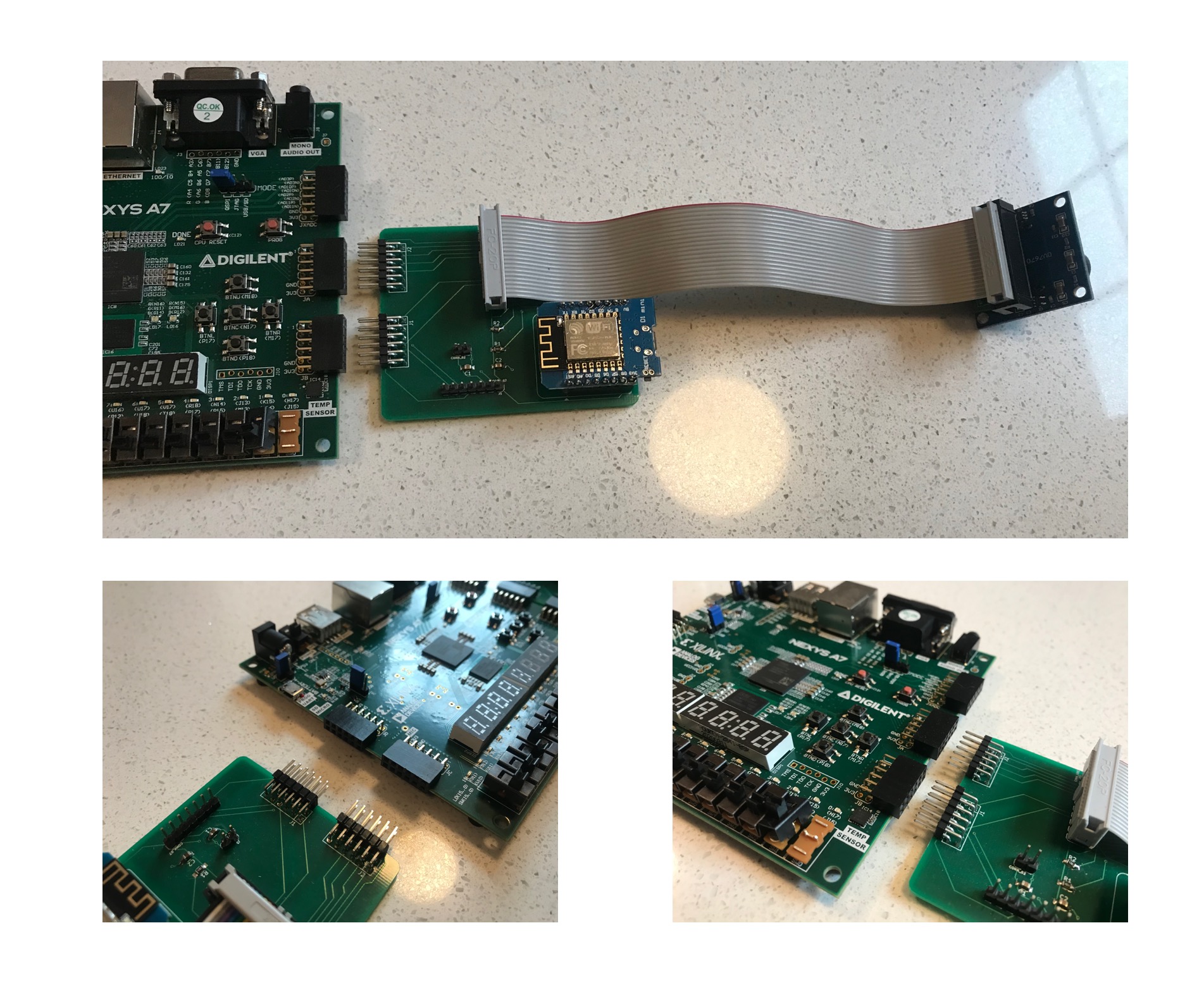
As written the code is written to work with the PMOD JA and JB ports (you can modify it to work with the two ports on the other side of the board relatively easily.)
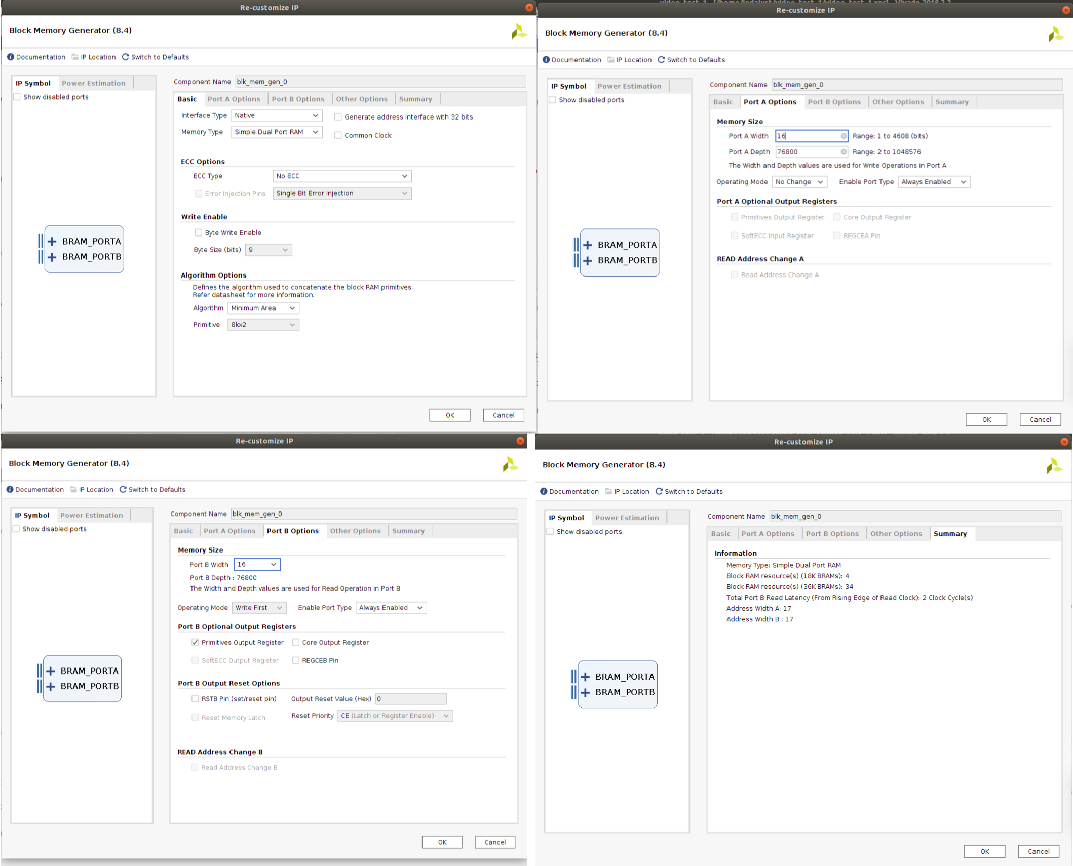
The only things you'll need to build locally within your project is a 65 MHz clock signal (just like in lab 3) and an appropriately sized BRAM IP module. Relevant settings for the BRAM are shown below! It is a dual port and enough to hold one frame of 320 by 240 image at 12 bits (I use the upper 4 bits of the 565 RGB data that gets sent from the camera...see the data sheet for details).
## Microcontroller
The FPGA just consumes video output data in this setup. It doesn't need to waste its resources setting up the camera since we use a microcontroller to more flexibally do that for us. For a few random reasons, I wrote the control software for the camera for an ESP8266. Why I chose this board and not another was really cost/form factor and that is it. I really just needed something with a programmable I2C bus, and I had a bunch of ESP8266 boards already.
Anyways, in order to program the ESP8266 to control the camera, you'll need to install Arduino. Then once you have that, Go to Tools>Boards>Board Manager, and search for ESP8266. Search for ESP8266 and install that when you find it. Then download the following program and open it
* ESP8266 Control Code
Go up to Tools>Boards and select LOLIN (WEMOS) D1 Mini Pro. Then program the ESP8266 with the code.
The code is basically a giant initial I2C register write to the camera that happens on boot-up. Then the code does nothing. Right now the code attached above has standard register write values to get the camera working decently. Totally feel free to experiment with these values using the register map found in the OV7670 dataasheet. If you want to change something, just change the value written to the register, then reprogram!
## Wiring
As far as the wiring that the board takes care of, the following pins are routed together. Again keep in mind the FPGA doesn't really control the camera, the ESP8266 controls it and sets it up. Then during run time, the FPGA provides it a clock signal on the XCLK line which the camera uses to supply data back to the FPGA on lines `D0` to `D7` and should use the `PCLK` and `VSYNC` and `HREF` lines for interpretation of that data.
OV7670 Pin | ESP8266 | FPGA pin
-------|-------------|------
3V3 | | 3V3
SIOC | D1 |
VSYNC | | PMODB 1
PCLK | | PMODB 0
D7 | | PMODA 4
D5 | | PMODA 6
D3 | | PMODA 3
D1 | | PMODA 1
RESET | 3V3 |
GND | GND | GND
SIOD | D2 |
HREF | | PMODB 2
XCLK | | PMODB 3
D6 | | PMODA 5
D4 | | PMODA 7
D2 | | PMODA 2
D0 | | PMODA 0
PWDN | GND |
[Wiring that the board handles]
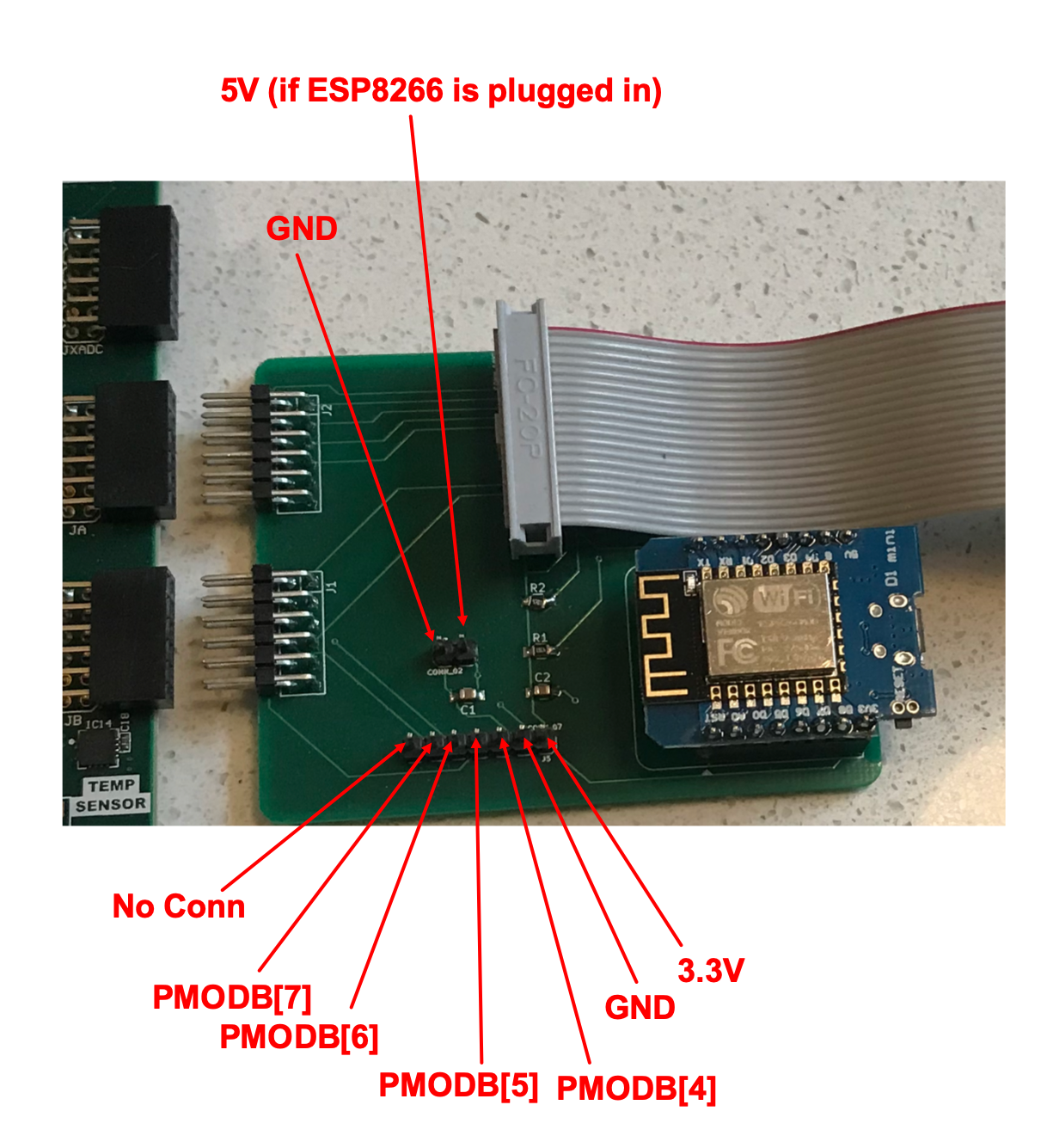
The board is designed to plug into a pair of PMOD ports, however it doesn't use all the pins so some of them are broken out in case you are running short and need access to them. Of course in my rush to get these boards made last fall I forgot to set up the silkscreen correctly so of course the pins are unlabeled. The extra pins are indicated and labeled below:
# Better Values for Camera:
The values below for the camera are probably a better starting point for a more natural lighting. The camera's automatic white balance (AWB) in general sucks and makes everything look like it is on Venus with yellowish tints, so this forces it to be off (as well as automatic gain control AGC and automatic exposure control (AEC)), and just lets you manually set your R, G, and B balance values (see the bottom/last few register writes). The values there made my camera look halfway decent, but you'll need to tweak depending on your situation/environment.
~~~~~~~~~~~~~C
uint8_t settings[][2] = {
{0x12, 0x80}, //reset
{0xFF, 0xF0}, //delay
{0x12, 0x14}, // COM7, set RGB color output (QVGA and test pattern 0x6...for RGB video 0x4)
{0x11, 0x80}, // CLKRC internal PLL matches input clock
{0x0C, 0x00}, // COM3, default settings
{0x3E, 0x00}, // COM14, no scaling, normal pclock
{0x04, 0x00}, // COM1, disable CCIR656
{0x40, 0xd0}, //COM15, RGB565, full output range
{0x3a, 0x04}, //TSLB set correct output data sequence (magic)
{0x14, 0x18}, //COM9 MAX AGC value x4
{0x4F, 0xB3}, //MTX1 all of these are magical matrix coefficients
{0x50, 0xB3}, //MTX2
{0x51, 0x00}, //MTX3
{0x52, 0x3d}, //MTX4
{0x53, 0xA7}, //MTX5
{0x54, 0xE4}, //MTX6
{0x58, 0x9E}, //MTXS
{0x3D, 0xC0}, //COM13 sets gamma enable, does not preserve reserved bits, may be wrong?
{0x17, 0x14}, //HSTART start high 8 bits
{0x18, 0x02}, //HSTOP stop high 8 bits //these kill the odd colored line
{0x32, 0x80}, //HREF edge offset
{0x19, 0x03}, //VSTART start high 8 bits
{0x1A, 0x7B}, //VSTOP stop high 8 bits
{0x03, 0x0A}, //VREF vsync edge offset
{0x0F, 0x41}, //COM6 reset timings
{0x1E, 0x00}, //MVFP disable mirror / flip //might have magic value of 03
{0x33, 0x0B}, //CHLF //magic value from the internet
{0x3C, 0x78}, //COM12 no HREF when VSYNC low
{0x69, 0x00}, //GFIX fix gain control
{0x74, 0x00}, //REG74 Digital gain control
{0xB0, 0x84}, //RSVD magic value from the internet *required* for good color
{0xB1, 0x0c}, //ABLC1
{0xB2, 0x0e}, //RSVD more magic internet values
{0xB3, 0x80}, //THL_ST
//begin mystery scaling numbers. Thanks, internet!
{0x70, 0x3a},
{0x71, 0x35},
{0x72, 0x11},
{0x73, 0xf0},
{0xa2, 0x02},
//gamma curve values
{0x7a, 0x20},
{0x7b, 0x10},
{0x7c, 0x1e},
{0x7d, 0x35},
{0x7e, 0x5a},
{0x7f, 0x69},
{0x80, 0x76},
{0x81, 0x80},
{0x82, 0x88},
{0x83, 0x8f},
{0x84, 0x96},
{0x85, 0xa3},
{0x86, 0xaf},
{0x87, 0xc4},
{0x88, 0xd7},
{0x89, 0xe8},
//WB Stuff (new stuff!!!!)
{0x00, 0x00}, //set gain reg to 0 for AGC
{0x01, 0x8F}, //blue gain (default 80)
{0x02, 0x8F}, //reg gain (default 80)
{0x6a, 0x4F}, //green gain (default not sure!)
{0x13, 0x00}, //disable all automatic features!! (including automatic white balance)
};
~~~~~~~~
Here's the camera with the gree gain turned all the way up( 0xFF (max value)):
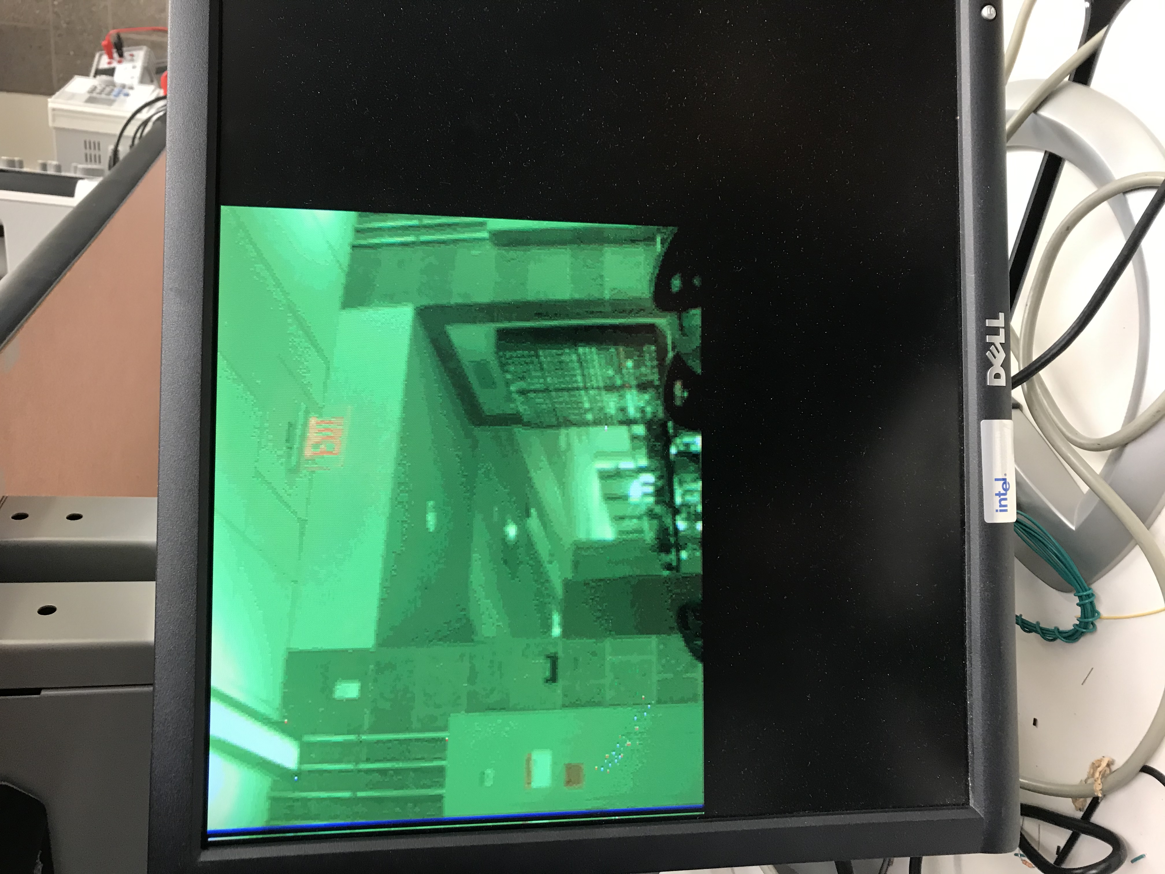
You can see everything is green...but what is also interesting, is things that have significant orange in them, stick out. If you're doing some object detection based on color tracking this might provide you another angle to get at some data.
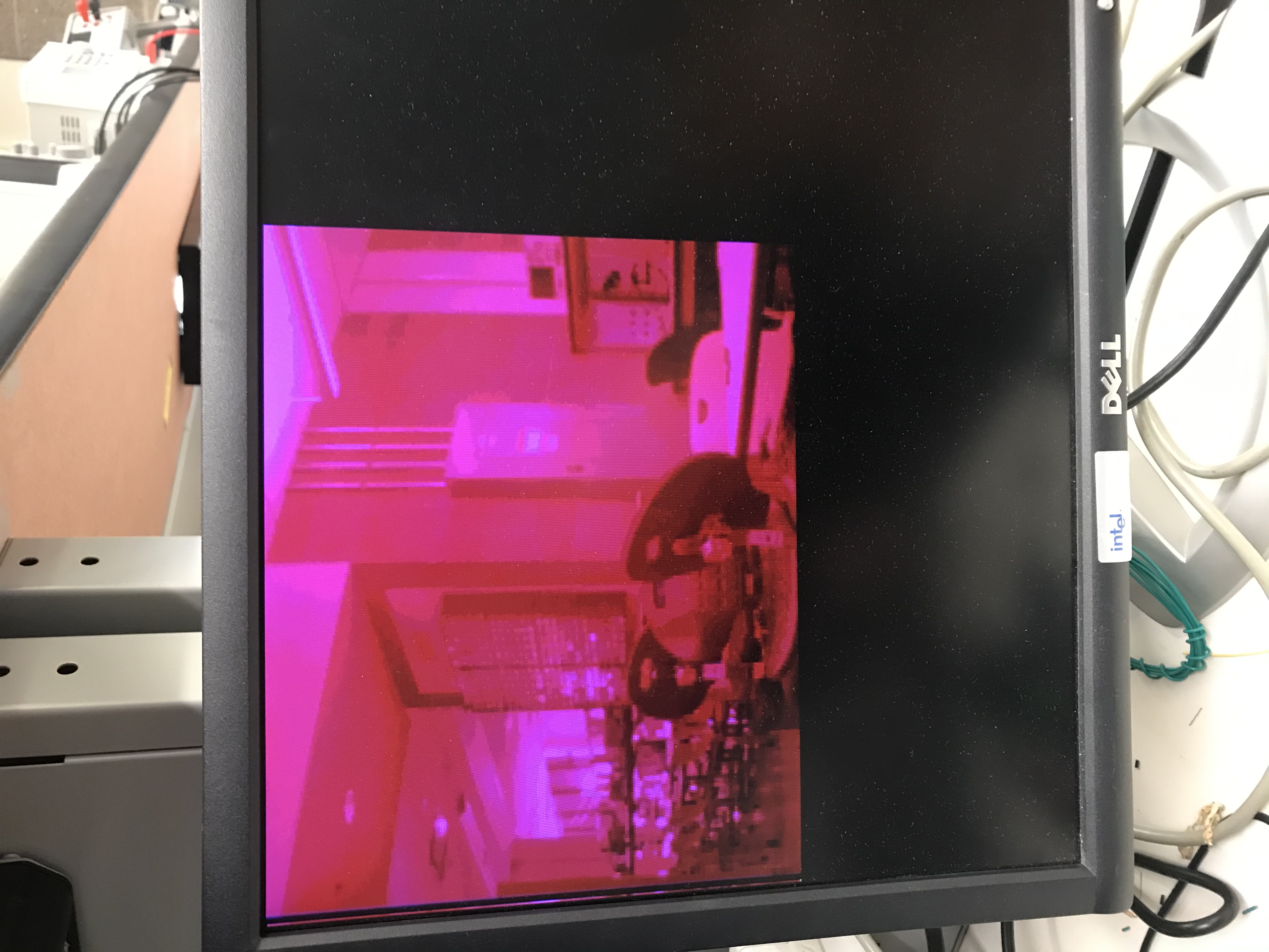
Cranking red and bringing green gain to zero gives this:
Email with any questions/concerns and/or post on Piazza!